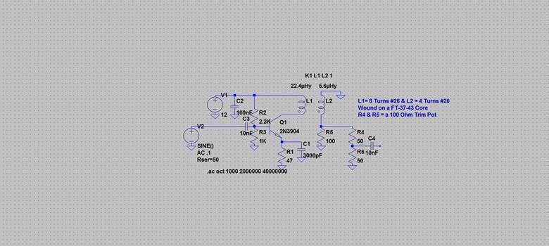
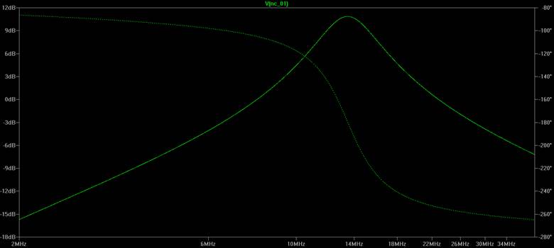
This is an evaluation of the amplifier circuit used in the bidirectional stage where one half is the Receiver RF amplifier and the other half is the Transmit Pre-Driver. The two resistors (R4 & R6) simulate a 100 Ohm trim pot which of course in parallel with R5 presents a constant 50 Ohm load to the stage. The center wiper is used as the output port. With the trim pot set at the 50 Ohm point the output has a peak at around 14 MHz and is good for 12 dB of gain. To insure stability on the transmit half, the input to this amp has a “T Type” 3 dB resistive pad inserted between the output of the Transmit Band Pass Filter and the input to this stage. The 50 Ohm pad has 8.2 Ohms for the series arms and a 150 Ohm for the parallel arm.
By in large the frequency of the peak in the response is mostly governed by C1. Changing the emitter bypass cap, C1 to say 100 nF drops the peak to 160/80 Meters. Lowering the cap to 2000 PF makes for a nice 17 Meter RF amp. The Ft for the 2N3904 is around 300 MHz (depending on who makes it) and thus represents a huge bang for the buck. The leaded version has a dissipation reaching 625 Mill-watts but the surface mounts are about 1/3 of that. The last bulk buy I made for a name brand cost me 4 cents a unit.